EFI
Performance Fuel Systems "101"
This is a summarized but complete overview of the proper way to
plumb a Mercury Racing EFI outboard powered boat.
Production EFI’s and ProMax series motors can benefit
from these guidelines however they will not need the same
size fittings, hoses or fuel pumps. These designs use vacuum
pumps to feed a self-contained system therefore the plumbing
is not as demanding. The majority of Performance Outboards
are crankcase injected Mercurys. Therefore, they are the
target of this topic.
We must start off by noting that this discussion applies to race boats, as
certain practices do not always agree with USCG/marine survey/ insurance
industry regulations. For example, the anti-siphon valve that no doubt came
with your new boat, does not go well with that new drag motor you are about
to install. The ultimate fuel system does not use stand pipes or shut-off
valves, but rather fittings in the bottom of the tank. The good news is that
outboard regulations are less addressed than their inboard counterparts.
Engines, exhaust manifolds, belts, pulleys, alternators all in the enclosed
bilge demand more attention than an outboard or two hanging off the transom.
The most common rigs do utilize stand pipes in their tanks, which can easily
be designed to work efficiently.
Perhaps, after some people finish reading this article, they may say “I
don’t have it like that” or “never had a problem so why
change it?” That may be so, but the beauty here is that the correct
method is very inexpensive and the owner can easily do it themselves. When
you do have an engine failure or are not running as quick or as fast as your
buddy with a similar rig, it is nice to be able to rule out improper fuel
delivery as the culprit.
We will not drag out fluid
dynamics calculations that take into account internal hose friction,
temperatures, or viscosity. That would be boring and unnecessary.
This article comes from 28 years in the racing business both with
cars and boats. Hardly a week goes by that we are not on the telephone
explaining these principles that we are about to cover.
OK, now for the fun stuff.
One single sentence sums
up this entire article.
“ Do not starve the suction
side of the High Pressure pump”
Starvation is commonly achieved in
many ways:
Small Hose
( we have seen people stretch
-6 hose over a -8 barb)
Small Fittings
(
Easily, the most common condition is the correct hose size coupled
to a fitting with too small an inside dimension)
Collapsed and Kinked Hose
(We serviced a 30’ offshore
cat with unmounted sponson bladders that worked the hoses to the
point of internal breakdown)
Stand Pipes - Too
Short, Cracked or Even Too Long
(plastic ones jammed to the bottom
of the tank always raise an eyebrow)
Horribly Restrictive Screens at the Stand Pipe Entry
(a sometime necessary
evil on boats with deteriorating built-in fiberglass tanks).
Most Often
the Biggest Problem Starts at the Very Beginning
(The “Hard” 90
degree fitting at the top of the tank’s stand pipe with the
infamous anti-siphon check valve barb may be lurking in your boat
at this very moment)
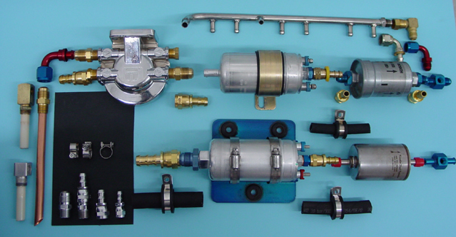
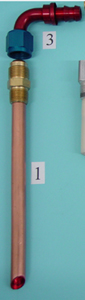 Figure
1 shows one simple way
of making a stand pipe for your existing tank. We use ½” o.d.
soft copper tubing (the kind that is sold in coils). Tanks usually
have a 3/8” pipe female threaded bung or bushing on the top,
so simply machine a brass 3/8” pipe male to -8 adapter so that
the straightened ½” o.d. copper tube slides inside.
Solder them together with silver solder (lead solder works fine as
well) and you are now well on your way to success.
Figure
1 shows one simple way
of making a stand pipe for your existing tank. We use ½” o.d.
soft copper tubing (the kind that is sold in coils). Tanks usually
have a 3/8” pipe female threaded bung or bushing on the top,
so simply machine a brass 3/8” pipe male to -8 adapter so that
the straightened ½” o.d. copper tube slides inside.
Solder them together with silver solder (lead solder works fine as
well) and you are now well on your way to success.
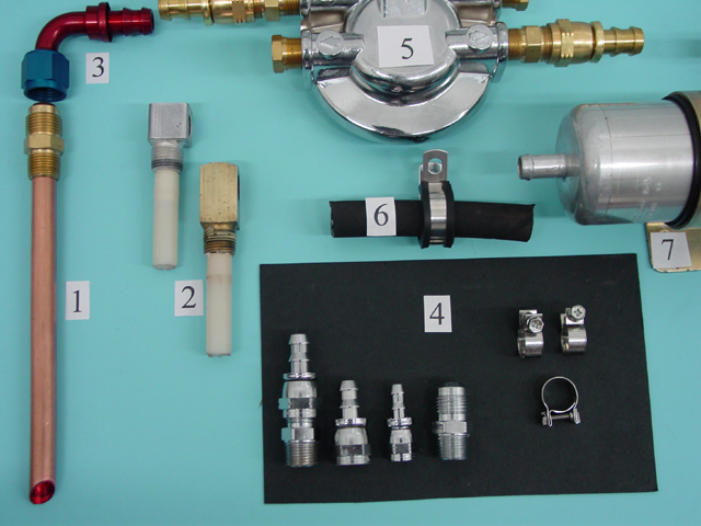
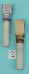 Figure
2 are examples of what you do not
want. These are however widely used and tolerable in another system’s design that
use transfer pumps to fill a “catch” tank. We will
discuss this later in the article.
Figure
2 are examples of what you do not
want. These are however widely used and tolerable in another system’s design that
use transfer pumps to fill a “catch” tank. We will
discuss this later in the article.
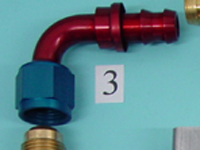 Figure
3 Top off the new -8 adapter with a TUBE 90 degree elbow. Do
not use any more 90 degree fittings en route to the high pressure pump
inlet (suction side of system).
Figure
3 Top off the new -8 adapter with a TUBE 90 degree elbow. Do
not use any more 90 degree fittings en route to the high pressure pump
inlet (suction side of system).
Figure 4 shows some samples of fittings that we had chromed. Fittings
are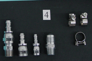 available
in a variety of metals and platings. Tube 90 degree elbows made in brass unfortunately,
do not seem to be available.
available
in a variety of metals and platings. Tube 90 degree elbows made in brass unfortunately,
do not seem to be available.
When you use brass fittings in salt water applications (which is correct) spray
them with a light coat of clear “krylon” to stall the inevitable
green discoloration. Pick and choose the fitting alloy that suits you. In most
of the rigs that we are concerned with in this discussion, electrolysis from
dissimilar metals will not cause a problem. It certainly would on larger center
console outboard boats left in marinas overnight. Shore power hook ups and
many electrical devices on board would make bonding and zincs mandatory. A
side note worth mentioning is to avoid the temptation to use stainless braided
hose assemblies especially in salt water applications. They may be necessary
in your blown 46’ Skater, street rod, or race car, but stay away from
then in your outboard hot rod. The following are two examples of why you should
not use them.
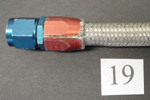 Figure
19 demonstrates electrolysis formed under the hose end
at the stainless steel braid. This hose assembly was removed
from the bilge of an outboard offshore race boat that was craned
out every afternoon. It never sat overnight in a marina. Stainless
steel and aluminum together may be the the best recipe for
electrolysis. Stainless braided hoses are risky in another
respect. In a thrash a steel fuel hose assembly accidentally
draped across a battery will no doubt spoil the weekend. Some
shops use plastic coated braided -4 trim hoses for this reason.
(they do turn ugly amber color however).
Figure
19 demonstrates electrolysis formed under the hose end
at the stainless steel braid. This hose assembly was removed
from the bilge of an outboard offshore race boat that was craned
out every afternoon. It never sat overnight in a marina. Stainless
steel and aluminum together may be the the best recipe for
electrolysis. Stainless braided hoses are risky in another
respect. In a thrash a steel fuel hose assembly accidentally
draped across a battery will no doubt spoil the weekend. Some
shops use plastic coated braided -4 trim hoses for this reason.
(they do turn ugly amber color however).
Figure 4 Also shows a few stainless
steel band clamps which are a tasteful choice over ugly, hose
wrecking worm clamps. These clamps are available in all necessary
sizes.
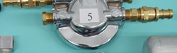
Figure 5 shows the sometime optional water/filter
base. We say optional because drag race and even river race boats (single engine)
consume most of their small tank’s volume on a daily outing. If you choose
not to use the water separator, be sure to fill the tank using a “race
car” funnel
with an internal bronze screen which removes water before it contaminates the
tank. Add a commercial coffee filter into the funnel to trap debris. This filter/funnel
set up will be easier to use if you install an “aero” style cap
onto the top of the tank. We prefer this method in lieu of a water separator
filter in the small EFI powered hot rod boat.
Larger hulls with big or multiple tanks, require water separator filters in
their system. Gasoline sitting in hulls for a time will collect moisture and
fueling in marinas may pose a problem.
Years ago, Mercury Racing generated a service bulletin for the ProMax series
motors prohibiting the use of hull mounted water separators. Mercury must have
had warrantee issues due to inadequate fuel system rigging, citing that their
powerhead mounted water separator was adequate; which it was. The problem arises
in the real world. The following is one example. You are returning from a weekend
of fishing and diving in your triple ProMax powered center console from Bimini
(Bahamas) to Miami. Halfway across in five to seven foot gulf stream seas,
your motors feel the ill effects of the bad load of fuel that you recently
bought. The only fix is to constantly dump the water separators that are not
safely mounted inside the bilge. Changing the motor mounted filter on the center
engine is an annoying process inside the shop, never mind hanging over the
transom while waves crash over you! The point of this story is that by properly
plumbing any boat’s fuel system, you can enjoy unexpected benefits that
may arise. When installed properly, all ProMaxes can safely run hull mounted
water separators without a problem.
Back to Figure 5 We
use a large style 3/8” pipe
water separator base. The large 3/8” pipe
openings (as opposed to Merc’s ¼” pipe one) allow us to
easily ream the inside passages to .400” to improve flow. Blending the
inside corners adds a nice detail as well. If you choose to install
a water separator filter in your rig, this is the one to use.
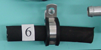
Figure 6 is a sample of -8 Push-loc
hose with a stainless steel Adel or cushion clamp. The -8 hose
is used for the inlet side of the two most common Bosch fuel
pumps. Be sure to double clamp this connection.
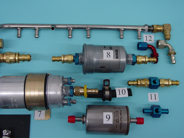
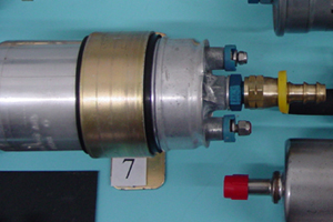
Figure 7 Shows
a Bosch High Pressure fuel pump. These pumps were original equipment
on Mercury Racing’s 260 and 280 H.P. motors. They can be
installed vertically and horizontally. It is important to mount
these pumps low in the hull. ( bottom of fuel tank is optimum)
These pumps have extremely tight internal clearances that require
clean gasoline. A vast majority of these pump’s failures
are caused by dirty fuel.
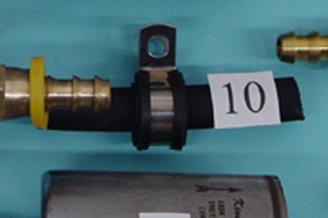 Figure
10 From this outlet
to the fuel rail use -6 (3/8”) hose. Alcohol
fueled
motors need larger, but that is a whole other
story.
Figure
10 From this outlet
to the fuel rail use -6 (3/8”) hose. Alcohol
fueled
motors need larger, but that is a whole other
story.
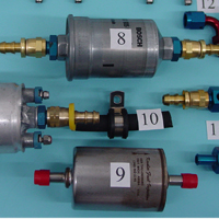
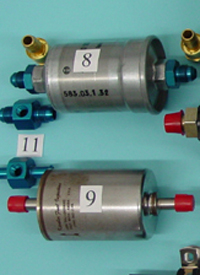
Figures
8 & 9 Inline filters protect the fuel injectors.
They are 8 micron rated and available with both fittings and barbs. You need
a filter with no less than 5/16” inside openings.
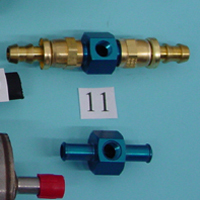
Figure 11 Fittings
with fuel pressure (1/8” pipe) ports are available for use with both
fittings and barbs. We also have pressure port fittings that thread
directly into the filter outlet. These are pictured elsewhere on
our website.
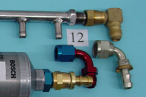 Figure
12 shows a few samples of -6 elbows
that attach to the 2.5 fuel rail inlet. The tube 90 degree hose
ends are a nice touch, but honestly, their importance is hard to
determine at this connection. Remember that the welded male flare
that comes on the Mercury 2.5 fuel rail is called -6 J.I.C.. Dash
6 fittings (and -12) come in two sizes; J.I.C. and S.A.E. You need
J.I.C. for this.
Figure
12 shows a few samples of -6 elbows
that attach to the 2.5 fuel rail inlet. The tube 90 degree hose
ends are a nice touch, but honestly, their importance is hard to
determine at this connection. Remember that the welded male flare
that comes on the Mercury 2.5 fuel rail is called -6 J.I.C.. Dash
6 fittings (and -12) come in two sizes; J.I.C. and S.A.E. You need
J.I.C. for this.
Fuel Rail Assembly
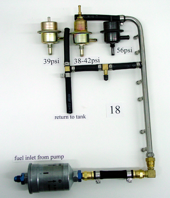
Figure 18 We
should mention a few things regarding the return from the regulator.
Ideally, it needs to be back into the main tank far away from the
pick-up. The Pro Max (“Laser”) style system came to be because the Coast
Guard cringes at the thought of a fuel line returning to the boat.
Finding an empty port in the main tank is the first choice. If
there is no fitting available, fabricate an aluminum (Stainless,
brass, bronze) splice to install into the fuel fill hose with an
angled fitting or barb to accept the return line. Once in the main
tank, the return fuel can cool and dissipate any air bubbles that
may have formed. If a line directly to the main tank is impractical,
it is okay to plumb the return fuel into an empty “in” port
on your water separator housing. This method has inadvertently
saved many people from problems. In the late eighties, we would
weld a fitting to the side of the Kinsler filter on the suction
side of the Weldon pump. This was a quick cure to remove the bog
from hard turning tunnel boats. Theoretically not the best method
but it worked. If you use a catch tank system, then use the port
you hopefully welded on top.

This photo shows pumps that are more necessary
for the competing outboard drag racer. Large
volume pumps seem to be necessary to maintain stable pressure on
the race track. These large pumps satisfy the needs of large 4 stroke
engines and yet we still need them on our little two strokes. Here
we can skip the theories and go with what works. Typically
a small fuel cell is used with fittings located in a small sump at
the rear bottom. A single -10 fitting must be installed, however
most cells come with two -8 fittings. Run the two -8 lines to a “Y” block
with a -10 outlet and you will be just fine.
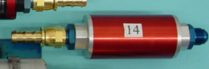 Figure
14 Aftermarket inline filters are available from a few sources.
Be sure they have -10 connections. Figure 13 this is the Weldon pump
which Mercury has supplied on and off since the 2.4 Bridgeport era.
These are noisy, expensive, battery killers, but otherwise fabulous
pumps. When purchased from Mercury Racing, they include the Kinsler
filter so Figure 14 will not be used.
Figure
14 Aftermarket inline filters are available from a few sources.
Be sure they have -10 connections. Figure 13 this is the Weldon pump
which Mercury has supplied on and off since the 2.4 Bridgeport era.
These are noisy, expensive, battery killers, but otherwise fabulous
pumps. When purchased from Mercury Racing, they include the Kinsler
filter so Figure 14 will not be used.
Figure 15 is a -10 hose sample with a stainless
steel Adel clamp. Drag racers can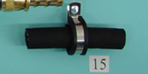 also
use the two -8 fittings in their fuel cells to feed two Bosch pumps in parallel
into a “Y” block having a -6 outlet. We had our customers use this
method back in the early-mid nineties. Some still use it today. If
your stand pipe style tank has a bung for a return line, you can install a
second stand pipe in that return line port. (you must find a new place for
the return hose) Bend this new pick up towards the front of the tank to help
solve slosh problems that can arise from larger un-baffled tanks. Join the
two stand pipes to a “Y” block and then complete the system.
also
use the two -8 fittings in their fuel cells to feed two Bosch pumps in parallel
into a “Y” block having a -6 outlet. We had our customers use this
method back in the early-mid nineties. Some still use it today. If
your stand pipe style tank has a bung for a return line, you can install a
second stand pipe in that return line port. (you must find a new place for
the return hose) Bend this new pick up towards the front of the tank to help
solve slosh problems that can arise from larger un-baffled tanks. Join the
two stand pipes to a “Y” block and then complete the system.
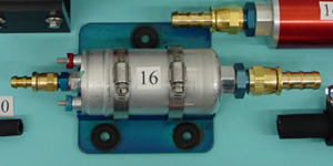
Figure
16 is our Bosch Magnum pump. It uses
a -10 inlet with a built-in 20 micron screen. This pump fits the
traditional mount, but we always end up fabricating custom ones.
Soon we will have a “standard” custom mount for sale.
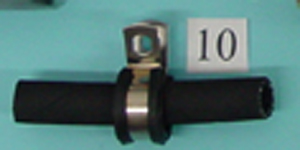
Figure 10 once again is a sample of -6 outlet hose.
Figure
8,9,11 are filters and fittings.
The final topic that we have not yet covered are boats that require “Catch
Tank Systems". This is where a low pressure
transfer pump fills a small vented tank (vent line feeds back to the main fuel
tank) from which the high pressure pump can draw the fuel. Big hulls, high
speeds, tight turns, and high seas all require this simple but necessary system.
Hard turning smaller tunnel boats can use this system as well, but a set-up
with just one pump often is preferred. These small single tank boats easily
can use custom tanks that feature baffles, sumps and one way trap doors to
accomplish anti-sloshing.
A common inexpensive transfer pump
is the “Red” Holley.
Do not waste your money on the “Blue” model as it is the same pump
with a different bypass spring. The “Blue” pump comes with a regulator
needed for carburetors. You will not use it so why pay for it? On vessels running
in salt water it is necessary to paint these pumps and mounts because they
tend to get ugly fast.
The pick-up side of a catch tank system is more forgiving than the other
type because the low pressure pump does the work from the main tank. "Hard"
90 degree fittings are prevalent in larger boat’s stand pipes due to
clearance issues (decks and bulkheads) and boat builder unawareness.
The fuel is then
pumped to the catch tank where hopefully the air bubbles will be dissipated.
The catch tank supplies the high pressure pump with a consistent and unrestricted
fuel supply and sends it on to the fuel injectors.
In closing, we cannot stress the importance of free flow to the inlet side
of the EFI pumps in all applications. Tees and 90 degree fittings are commonly
used by people because they lay out nicely on a bulkhead and because they are
space savers. “Hard “90
degree fittings are a commonplace at the inlet side of water separators to
avoid “unsightly” loops in the hose. Here is an old rule of thumb
to keep in mind. A “hard” 90 degree fitting on the suction side
is like adding 15’ of length to your hose. Give your current lay out
a closer look; you may be shocked to see how restrictive it is.
Hopefully, the outboard hot rodder can benefit from these simple guidelines.
The properly rigged boat will give you safety, reliability, and top performance.
See
you at the races,
Joe and Marty Signorelli
.